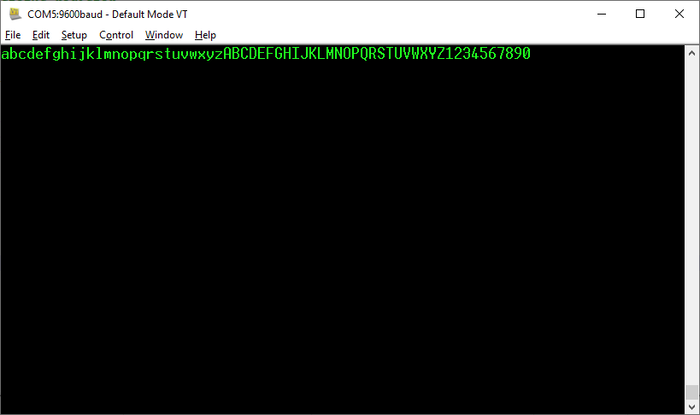
These programs use the serial port on the Altair to echo back characters that were sent to it.
Serial communication works by sending each bit individually. Multiple bits get sent one after the other. There can also be several start bits which are sent before the data. There can be a parity bit sent after the data which will either make the value have an odd or even number of 1s depending on the configuration. Finally there can be a number of stop bits. The start and stop bits are used to help the receiving device identify when data has been sent. The speed of the transfer is measured as a baud rate. This is a symbol rate and not technically a bitrate as it includes the start, parity and stop bits.
The serial connection on the Altair would have been connected to a terminal or a teletype. These are devices that have a keyboard for entering in characters and display characters either on a screen or print it on a piece of paper. When a key is pressed on the connected device the ASCII value of that character is sent to the device. AN echo program simply sends that same value back to the device which causes it to get displayed on the screen or printed on the paper.
 Serial Echo
There are two different possible serial boards on the Altair 8800, the 88-SIO board and the 88-2SIO board.
88-SIO
The 88-SIO board is the earlier and simpler of the two boards. Most of its configuration is done by modifying the board itself. It uses two IO ports, 00H for control/status and 01H for data.
When reading from the status register, bit 7 is low to indicate that data is ready to be sent and bit 0 is low to indicate that data has been received. When writing to the control register, bit 0 is set to 1 to enable interrupts when data is received and bit 1 is set to 1 to enable interrupts when data is sent.
Interrupts cause the computer to execute an RST 7 instruction which causes the CPU to jump to the address 0038H.
88-SIO Status Echo
EchoSIO.asm
This program echoes data by reading the 88-SIO status register to determine when a character has been received. It starts by executing an IN 00H instruction to read the 88-SIO status register into the accumulator. An RRC instruction is then executed which rotates the accumulator right and sets the carry flag based on the least-significant bit. The JC instruction is then executed to test the carry flag. If this value is 1 it indicates that no value has been received which causes the program to jump back to the beginning to check the status register again. If the value is 0 then it doesn't jump and the program continues on. It then executes an IN 01H instruction to read the character received and then executes an OUT 01H instruction to echo it back. The program then jumps back to the beginning to wait for another character.
88-SIO Interrupt Echo
EchoSIOInt.asm
This program echoes data by waiting for an interrupt from the 88-SIO board. The program starts by initializing the stack pointer, which is required for the interrupt to store and return to the address currently being executed. Next it sends out a value of 01H to the 88-SIO control register which enables input interrupts on the IO board. After this it executes the EI instruction to enable interrupts on the CPU. Finally the program goes into a NOP loop. The interrupt handler at 0038H starts by pushing the accumulator onto the stack. This is required because we don't know what the rest of the program is doing and the value in the accumulator is going to be trampled by the program reading in a character. It then executes an IN 01H instruction to read the character received and then executes an OUT 01H instruction to echo it back. It then pops the accumulator off the stack to restore it, re-enables interrupts and then executes an RET instruction to return to wherever the computer was previously.
88-2SIO
The 88-2SIO board has two serial ports and has more options for configuring the device through the control register. One serial port uses the IO port 10H for its control/status register and 11H for its data register while the other uses 12H and 13H.
Bits 0 and 1 of the control register are used to control the baud rate with a value of 11 used to reset the serial port. Bits 2-4 control how data is sent. Bits 5 and 6 control how interrupts work when data is sent and bit 7 enables interrupts when data is received.
88-2SIO Status Echo
Echo2SIO.asm
This program is very similar to the 88-SIO one except it starts by sending a 03H and a 15H instruction to the board. The 03H value resets the board while the 15H value configures it to use 8n1 (8 bits, no parity, 1 stop bit). The rest of the program is identical except it uses the 11H port.
88-2SIO Interrupt Echo
Echo2SIOInt.asm
This version of the program uses interrupts with the 88-2SIO board. This program is very much a combination of the non-interrupt 2SIO board and the SIO with interrupt program. The second control value sent to the device is 95H to also enable interrupts on the device. The rest of the program is very much like the 88-SIO with interrupts program except using the 2SIO addresses.